Sunday, July 31, 2011

Counting Seconds (Video)

It's not necessarily riveting, but here is a video which shows the tube counting from 0-9 and back again at 1Hz.


I am using a different tube than I intend to use in the future. Mostly that's because it came with a convenient solderable socket. Anyway, this was made possible by the use of a binary counter (SN74F163A) and a Quad-NAND gate (74F00) pulled from an old oscilloscope I tore down. Thanks to some help from a few people over at allaboutcircuits.com!

Sure, the wall outlet signal reduced to 1Hz from my previous post seems to work great, but the added "complication" of having to use a NAND gate with the counter I purchased makes this method a bit cumbersome. I will likely purchase or try to find another counter. Once I work this out, I will post updated schematics.

share on: facebook

Wednesday, July 27, 2011

Success! Let the counting begin

I have been struggling with a particular issue for several weeks now. Even though I get a seemingly perfect TTL (0-5V) pulse every time the 60Hz AC signal inverts, the IC counters all put out erratic signals which are not a simple divisor of the 60Hz signal. I thought originally that I had fried the IC's, but I tried several types of counters and ended up with the same result. I tried putting in capacitors almost everywhere, hoping that I could solve this by smoothing out the signal. I even set it up so an transistor made a more aesthetically-pleasing square wave (I decided to leave the transistor in).

After being infuriated for ages about this issue, I finally stumbled upon a forum post which noted that the rise of the signal from the 60Hz signal may not happen as smoothly as expected. In other words, small fluctuations could cause the IC to get tripped up and start pulsing faster than it should. Apparently, I was lucky the first time when I set up the initial timing circuit.

The solution: a Schmitt trigger.


It is a positive feedback that pulls the signal up once you hit a particular threshold. The type I chose was an "Inverted Schmitt trigger". These are often used to debounce a switch. I happened to have a quad op-amp IC laying around from another project. After hooking it up with three resistors, I got a perfect 10Hz output from the counter/divider I thought I had fried!


All soldered in:


Here is the new schematic:

Moving onwards!

share on: facebook

Saturday, July 16, 2011

Home-Made Enclosure - Main Board

I am waiting for the IC's to arrive from Digikey, so I decided to start working on the enclosure. After finally purchasing a Dewalt router so I can use the 50 new router bits my parents gave me for Christmas, I set out to build the main enclosure out of wood. I believe I have cherry-laminated plywood (correct me if I'm wrong), which I carefully beveled at 45 degree angles on the inner edges. After assembly using glue and finishing nails, I filled in the nail holes and sanded it down. Personally, I am really impressed with myself. This job took about 4 hours, but I bet I could get it down to maybe 2 hours or so if I were to do it again.


The dimensions are 4"x7"x2" and it is open underneath. When the circuitry is complete, I will make a bottom plate for the board to sit on and drill the holes for the wires. I'm still trying to decide what finish the box will get. By the way, my wife has convinced me to make the small nixie tube boxes (where the tubes will actually be located) out of wood as well. I might chronicle the construction of those pieces.

share on: facebook

Wednesday, July 13, 2011

Lighting a Tube!

I have finally taken some pictures of a Nixie tube lit up using the power-supply I built.


Note the new AC transformer. I will be sure to update the schematic once I get the new IC's.


share on: facebook

Sunday, July 10, 2011

Annoyances with Power Conversion

In the past post, I gave the full schematic of the nixie clock, but I did not completely explain the resistor that goes from the "neutral" lead to ground. That was simply because I wasn't sure what it was for!

Turns out the transformer is not a 9VAC transformer, but a 24VAC transformer instead! The resistor is voltage dividing the output to 9V. This wouldn't be a problem, except that when pulling higher currents from the transformer for, say, turning 9VDC into 170VDC, the current prefers to pass through the resistor instead of powering the device!

Basically, I would read no voltage from the transformer when I hooked up the Boost Converter. Arrgg.

Before realizing the purpose of the resistor, I removed the resistor and gave it a shot. Yay, I get 170VDC from the boost converter, but I found out a few days later that I ended up frying the decade counter IC's with 12+ VDC. Whoops!

So, what did I do? First I thought I would wind a new coil out of the existing one. I found this awesome tutorial on how to change the output voltage of the secondary coil by reducing the number of windings. After chiseling away the laminated segments of the core one by one, unwinding the mess of wire for the secondary to count how many turns there were, rewinding a fewer number of turns, and finally jury-rigging back the laminated segments, I got a nasty looking temperamental ugly stepchild of a transformer which jiggled and rattled at 60Hz on my desk like a buzzing bee! Yeah, it outputs 12VAC, but there is no way this thing is going in the final clock unless it ends up being an alarm feature. Yeah, I learned how these transformers are constructed, but in reality, I think I wasted about 3 hours of my time.


In defeat, I went out and bought an appropriate 120VAC to 12VAC transformer from RadioShack for around $3. I will post pictures of the reconditioned device soon.

share on: facebook

Sunday, June 19, 2011

AC Signal Conversion Schematic


I finally had a bit of time and I went ahead and finished the schematic for AC signal conversion. The schematic shows how I get a DC signal from 120VAC at 170V, 9V, 5V, and an oscillating 5V signal at a rate of exactly 1Hz. Please let me know if you see any errors. By the way, I read a while back that this method of converting AC to DC is supposed to be inefficient, but I can't say exactly why. If anyone has any suggestions to get a more efficient 9VDC signal, I would really appreciate it.

Next: need to alter the already-made power supply to incorporate this new transformer and circuits.
share on: facebook

Tuesday, June 7, 2011

Moving to the dark-side: AC-signal conversion

I mentioned in the previous post that I need to count the 60Hz oscillation from the wall AC in order to obtain good timing for my nixie clock. The problem is that I have never messed with AC electronics before, so I had to start with the basics.

I found an old AC to 9VDC wall adapter and tore it apart. I was surprised to find out how simple the design was, although I seem to remember that this method of converting to a DC signal is extremely inefficient. All it contained was a transformer with 120VAC in and 9VAC out. One of the leads on the 9V output was attached to a diode in serial (1N-4004, 1Amp) and the other was attached to a 620 Ohm 1/2 Watt resistor in serial.

This revelation was spectacular! This transformer is completely and utterly unregulated, which means that the positive lead (one with the diode) oscillates somewhere between 9V and 0V at a frequency of 60 Hz with the AC input with respect to the ground lead (one with the resistor). Only with a capacitor added in serial would this signal be smoothed out.

I set out to split the positive lead into two components - one that has a steady and regulated 9VDC output (to be converted to 5VDC) and the other which oscillates between 9V and 0V. For the 9VDC, I added a 330uF (16V) capacitor in parallel to ground. I converted that to 5VDC in the same fashion as I did for the high voltage power supply. For the oscillating signal, I left out the capacitor and divided the voltage, using resistors, down to 5V (I tested this on the 9VDC signal first). I'll put up the schematic of this soon. Now I have a steady 5VDC voltage and an oscillating 5V to 0V signal at a frequency at 60Hz!


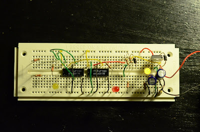
The previous image shows the components used for the 5VDC and oscillating 5V to 0V signal on the right (everything to the right of the red diode). I added another capacitor after the MOSFET just to make sure everything was properly smoothed out. The yellow diode to the far right indicates that the device is powered. The rest of the stuff (red diode and to the left) is used for counting.


I used two NTE4017B decade counting circuits which conveniently let you count between 1 and 10. Go to www.alldatasheet.com to find information on this circuit. The first one (right) counts up to 10, which means that a pulse is emitted from the circuit at a frequency of 6 Hz. The second one (left) counts up to 6, which means that a pulse is emitted from the circuit at a frequency of 1 Hz. The red diode flickers at 6 Hz and the left yellow diode flickers at 1 Hz. The two resistors on the far left do nothing (sorry, I forgot to remove them before I took the pictures!)

Again, sorry, I will submit schematics soon. I only put this together yesterday.

Until next time!


share on: facebook