I mentioned in the previous post that I need to count the 60Hz oscillation from the wall AC in order to obtain good timing for my nixie clock. The problem is that I have never messed with AC electronics before, so I had to start with the basics.
I found an old AC to 9VDC wall adapter and tore it apart. I was surprised to find out how simple the design was, although I seem to remember that this method of converting to a DC signal is extremely inefficient. All it contained was a transformer with 120VAC in and 9VAC out. One of the leads on the 9V output was attached to a diode in serial (1N-4004, 1Amp) and the other was attached to a 620 Ohm 1/2 Watt resistor in serial.
 This revelation was spectacular! This transformer is completely and utterly unregulated, which means that the positive lead (one with the diode) oscillates somewhere between 9V and 0V at a frequency of 60 Hz with the AC input with respect to the ground lead (one with the resistor). Only with a capacitor added in serial would this signal be smoothed out.
I set out to split the positive lead into two components - one that has a steady and regulated 9VDC output (to be converted to 5VDC) and the other which oscillates between 9V and 0V. For the 9VDC, I added a 330uF (16V) capacitor in parallel to ground. I converted that to 5VDC in the same fashion as I did for the high voltage power supply. For the oscillating signal, I left out the capacitor and divided the voltage, using resistors, down to 5V (I tested this on the 9VDC signal first). I'll put up the schematic of this soon. Now I have a steady 5VDC voltage and an oscillating 5V to 0V signal at a frequency at 60Hz!
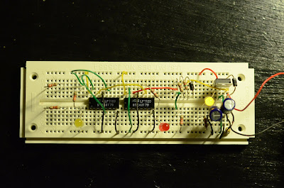
The previous image shows the components used for the 5VDC and oscillating 5V to 0V signal on the right (everything to the right of the red diode). I added another capacitor after the MOSFET just to make sure everything was properly smoothed out. The yellow diode to the far right indicates that the device is powered. The rest of the stuff (red diode and to the left) is used for counting.
I used two NTE4017B decade counting circuits which conveniently let you count between 1 and 10. Go to www.alldatasheet.com to find information on this circuit. The first one (right) counts up to 10, which means that a pulse is emitted from the circuit at a frequency of 6 Hz. The second one (left) counts up to 6, which means that a pulse is emitted from the circuit at a frequency of 1 Hz. The red diode flickers at 6 Hz and the left yellow diode flickers at 1 Hz. The two resistors on the far left do nothing (sorry, I forgot to remove them before I took the pictures!)
Again, sorry, I will submit schematics soon. I only put this together yesterday.
Until next time!
share on: facebook


No comments:
Post a Comment