Tuesday, June 7, 2011

Timing is Everything

BRIEF RANT: What is wrong with Radioshack and Fry's electronics!? I understand that if you are like most of my friends you will roll your eyes at what I'm about to say, but if you are an avid electronic hobbyist, I hope you understand my frustration. The problem is that I can't find any stupid crystal oscillators! As I mentioned briefly in my previous post, they provide very accurate pulses at a high frequency that you can use to provide very precise timing. They are ubiquitous in hobby radio applications (here is why I am appalled at Radioshack) and are necessary to run programmable circuits, which are widely available at Fry's, WHO DOES NOT SELL CRYSTAL OSCILLATORS! So, if you want to get every component at one store EXCEPT the one you desperately need, go to Fry's.

Well, at least I thought I needed a crystal oscillator...

Turns out you can get extremely accurate timing based off of the 60Hz AC signal from your wall outlet. Apparently the power company will oscillate the AC signal at exactly 60 pulses a second every minute, every hour, and every day of the year. It's supposed to be one of the most accurate methods of keeping good time. I have seen a few examples of circuits using this method of timing on Hackaday.com, but I felt they left out a few important points. Hopefully the next few posts will clear this up. The only issue is that my nixie power supply runs off of 9VDC. So I have decided to put a transformer directly onto the board, meaning I will have direct access to the oscillating signal. Unfortunately, I have never-before tinkered with an AC signal.

See you next time!


share on: facebook

Nixie Tube Power Supply (Part 2)

Sorry about the lack of posts lately. I have been crazy busy with work, not to mention the three vacations I have had back to back (believe it or not, that can be a bit tiring--but don't get me wrong, I would do it all over again). Anyways, enough about me, I have pictures of the power supply!


That large black cylinder is the inductor (in case you were wondering). Look at the previous post for a schematic. I got almost every single part from Digikey. Aside from the inductor, I received enough parts to make almost five of these power supplies with a final cost of around $40-$50. Not too bad if you ask me. Buying in bulk obviously reduces the prices even further. Not shown is the 9VDC power supply, which I am currently borrowing from my other nixie clock.


I thought originally that I had purchased a high-voltage 2.2uF capacitor (C4), but it turns out I missed it when I did the ordering. The large gray rectangular box is a 0.68uF capacitor rated at 310V. I yanked it from a broken computer power supply I had sitting around. I would have been pretty angry if I hadn't found it... crisis averted! Turns out the 0.68uF capacitor works just fine instead of the 2.2uF cap.


The back-side doesn't look too pretty, but it's a project board, what do you expect?? I'll upgrade to PCB (printed circuit board) eventually!

So, success! I get an output of 170VDC (adjustable by adjusting the potentiometer--the blue rectangular box) out of the red wire (red means DANGER!). I also get a convenient 5VDC output I can use for the integrated circuits out of the yellow wire. Black is common for both outputs. I'll see if I can't eventually post a picture of the nixie tube hooked up. I know this works from experience, but it would be nice to show it on the blog.

Next, I need to figure out a way to get the timing on the clock right. This has been bothering me for a bit since I would like to avoid using PICs (programmable integrated circuits), but the only reliable way to get a timed pulse that will be accurate over months or years with a DC input is to use a crystal oscillator. These puppies put out thousands to millions of pulses per second... bringing that down to 1 pulse per second will take a large number of divider circuits. Ok, I'll get back to you on this! 'Till next time!

share on: facebook

Sunday, May 15, 2011

Nixie Tube Power Supply

Sphere's Nixie Tube Page specifies that the IN-14 tubes require a 170-180VDC power supply and a 33kOhm resistor in series (before the anode). Most AC to DC power supplies provide between 3.3VDC to 15-20VDC. I also want to have 5VDC for logic circuits. For the first nixie clock (Nixie 1.0), I purchased a boost converter kit, something like this one. For me, it was a "black box" when I soldered the components on, but I knew I needed to figure out a bit more about how it works if I intended on making my own from scratch.

I manually copied the circuit diagram into Eagle Cadsoft (you can get a limited version for free which should work great for this project from here). Below is a picture of the circuit diagram I drew up. If you need help with using Eagle (...and you probably will because it is not intuitive), take a look at some youtube videos. There are comprehensive tutorials out there... that's the way I learned how to use it.


So, this schematic looks daunting, and to tell you the truth, I'm not completely certain what every part does, but I will try my best to explain what I do know. Some of my information came from this helpful website.

I have +9VDC coming in up top. The C1 capacitor is there to smooth out the DC input in case there is any ripple. This may not be necessary, but it can't hurt. A point of warning, make sure that all of the capacitors are rated for the appropriate voltage.

The inductor (L1) is the business end of things and is hooked up at one end directly to the 9VDC and the other to a miriad of other components. The purpose of the other components is to switch on and off the flow of current in order to maintain a high potential (160-200VDC). After the diode (D1), we have 160-200VDC. So what are all of the other components?

The C3 and C4 capacitors are high-voltage capacitors which are there to buffer the output voltage. The integrated circuit (IC) is a 555 timer. The 555 timer is there to rapidly switch the transistor (Q1) on and off. When the transistor is closed (passes current), the inducted current goes to ground. Once switched open, the current is forced to pass through the diode. If this process is repeated at a rate which is faster than the decay time of the current running through the inductor, you get a potential build-up passed the diode. I will talk a bit more about how the 555 timer works in general later, but right now you have to believe me that many of the remaining components are just there to ensure the switching is rapid.

Lastly, the voltage has to be regulated, or the voltage will keep rising to no end. This is done using the resistors R3, R4, and R5. R4 is adjustable, so you can adjust the final voltage. This resistor series acts as a voltage divider, allowing the transistor (T1) to begin conducting once we reach 160-200V. Once T1 conducts, the voltage is dropped, and increases the frequency of the 555 timer cycle, providing active feedback.

Now that I know how this works, I can begin soldering! See you next time.

share on: facebook

Saturday, May 14, 2011

The Plan

Ok, so Nixie 2.0 needs to be different from all of the other nixie clocks out there. I'm tired of seeing the same thing all the time. People make neat boxes and enclosures, but they sometimes lack that coolness factor.

After thinking about it for a while, I thought it would be neat to have modular units for the tens hours, hours, tens minutes, and minutes. I admit, I'm getting this idea from a ThinkGeek product, but I don't think the final product will look anything like their Matrix Cube clock. I made a simple sketch, which is shown below:

Yeah, it's crude, but I hope you get the general idea. There will be a base which contains all of the business-end things--the power supply, timer circuits, and buttons. Each of the nixie tubes will be contained in a very small box which will be wired to the base. All of the boxes for each of the tubes will be able to nest into a depression in the base, or they can be moved around at will. I wonder if I need to put something heavy at the bottom to make sure they don't tip over. I have thought about maybe even using a monitor cable as the method of supplying the wires to the tubes, allowing me to unplug each nixie tube box if I want to exchange it, or it may allow me to put the nixie tubes in confined areas, hiding the base.

The point here is that I want the base to be as skinny as possible, so I will try to compact all of the components into as small of an area as possible. I really have no idea about the location of the buttons, the style and material of the box, or how I might add the neon lamps. All I know now is that I need to make as small of a power supply as possible, on the cheap, from scratch.

share on: facebook

Nixie Tubes!

Nixie Clock 2.0 has some pretty neat inspiration -- a plethora of nixie tubes. My older brother gave me a bunch of Russian IN-14 tubes. Take a look at this website, they have an insane number of tubes for sale. He got them on ebay still attached to a display rack:

Of course, I have already taken a few of them off of the rack (desoldering these was quite a chore). You can see on the far right that they come with a few neon lamps, which might be good for the colon between hours and minutes? All of these items take 170VDC and each of the nixie tubes has an anode and 12 cathodes (one for each of the digits, 0-9, and the last two are for decimals before or after the digits).

So, I think you can probably already get an idea of the issues associated with making a clock out of these tubes. They take very high voltage (although very low current) and require switching between each cathode in order to display any one of the digits. I also need 5V for switching using integrated circuits. I would like all of this to be in a compact design. Speaking of design... next post. See you then!

share on: facebook

Nixie Clock 2.0

So, it's time to make a nixie clock! To those who don't know what nixie tubes are, take a look at the wikipedia page: http://en.wikipedia.org/wiki/Nixie_tube. My older brother gave me a bunch of these over the past year. They come in a number of types and sizes, but they all have a similar orange-red glow to them. They were used as an early display technology, but now people mostly use them for making retro displays such as clocks.

I have already made a nixie clock. A picture of the clock is shown below (thanks Lance for taking the B&W film picture of me). I learned a great deal about electronics from the project, but I used an Arduino (user-friendly programmable input/output device) for the project and purchased a kit for the power source. It does have a lot of features, like two alarms, temperature reading (shown below in degrees celsius), 12-hour/24-hour format, sleep setting (where it turns the tubes off at night), and an auxiliary input which does nothing right now. Still, I wanted to do everything from scratch and not rely on convenient technology.


So, this blog will now be dedicated to updating the progress of making the nixie tube clock completely from scratch, but without the fancy extras. I will start with a 9VDC power supply and make all of the components from either available or purchased resistors, integrated circuits, capacitors, transistors, etc. The next post will explain what my design will be and I will follow with updates on everything from the power supply to controlling the tubes and constructing the actual clock.

I might also show how I made the first nixie clock (Nixie 1.0). I'm pretty proud of it.

Enjoy!

share on: facebook

Friday, January 29, 2010

Make your own Boomerang!

About three weeks ago my wife and I went to a local library book sale. Among many other great finds, my wife stumbled upon a book on making boomerangs--and not just the normal "Australian" style. Apparently, cross-stick boomerangs are the most fun to make (and easiest to use). So, I just had to get my hands dirty.

First I had to get two thin pieces of wood (1/8" thickness works best) by 1 1/2" by 2 ft. Unfortunately, I didn't have any sitting around this past weekend... but I really really wanted to try this out. So, I carefully rip-sawed two pieces of 1 1/2" by 1/2" pine. It was an annoying process, just look at the setup:

...but alas, after 30 minutes or more of fiddling, I had two pieces of wood with the right dimensions. If I hadn't been so hasty, I could have just gotten some scraps from Lowe's or Home Depot (yeah, they give that stuff away), although you should make sure you're getting pine, or at least something not too heavy. By the way, apparently balsa-wood won't work well for boomerangs--it's actually too light!

Anyway, on to the tools. You will at least need a very sharp knife and a drill (later) to do this, but a few other tools are nice to have. I found this weird chisel-like tool at a barn sale last week (center-left below), but everything else I had already. The clamps are nice to have when you're whiddling away, and some sort of measurement tool helps. The wood-gouging tools are useful for lightening the boomerang, but you may find out you don't need them.


So, the directions say that a tapered edge toward from the "spinning direction" is usually added. Since this is a right-handed boomerang, the spinning direction is counter-clockwise. I marked a rough tapered edge and wrote "top" on the correct side so I wouldn't get confused at the later step when I whiddle the wing (although, I actually completely messed this up and got it backwards in the end anyway!... I hope it won't change the outcome too much.)


I cut this first tapered edge away using a utility knife, but anything should work. In all honesty, this is the easiest part by far. Once finished with the first taper, I traced it onto the other board and kept working through all of them until they were finished. Now we begin to get to the interesting stuff...

It is very crucial that you now balance the sticks. In other words, because of my poor manufacturing of the sticks, one end is likely heavier than the other. So, just find the center by balancing it on your finger (or even better, the eraser on the end of a pencil) and mark it. Next, measure 1-inch in each direction and draw lines perpedicular to the length of the stick (see below).

You can see the tapered edge I made in this next picture.


I gouged out the back using a gouging tool. I'm not really sure if it is necessary. I made gouges approximately 2 inches long in sets of three across the entire underside of the sticks, except for the area where the sticks overlap.


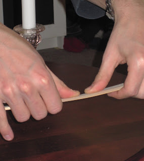
After doing the cutting and gouging, I bent the sticks using a candle. You want to bend the sticks so that the boomerang has a low center of gravity. This will ensure stable flight. I heated each stick approximately 1/3 from the center to each edge over a candle for about 20-30 seconds. I then immediately pulled it away from the candle and put a slight upward bend into it. It took a while to get it right, and nothing caught on fire. It's pretty foolproof.


Here you see one of the sticks bent on both sides. I'm not sure what the angle is, but each end is raised around 1/2" on a flat surface.


I drilled a hole in the centers of each stick (marked earlier) for a 6-32 bolt. It doesn't matter what size you use, but try to keep it small. The bolt was around 1.5" long with both a standard nut and a wingnut. The excess length of the bolt allows you to catch it in flight as it comes back toward you, and the wingnut lets you tighten the bolt when it becomes loose.


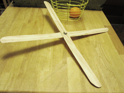
And here is the finished product! It flies great even though I have the directionality backwards. I did paint it, but I was not able to take a picture before giving it to my younger brother as a gift.


share on: facebook