Sunday, June 19, 2011

AC Signal Conversion Schematic


I finally had a bit of time and I went ahead and finished the schematic for AC signal conversion. The schematic shows how I get a DC signal from 120VAC at 170V, 9V, 5V, and an oscillating 5V signal at a rate of exactly 1Hz. Please let me know if you see any errors. By the way, I read a while back that this method of converting AC to DC is supposed to be inefficient, but I can't say exactly why. If anyone has any suggestions to get a more efficient 9VDC signal, I would really appreciate it.

Next: need to alter the already-made power supply to incorporate this new transformer and circuits.
share on: facebook

Tuesday, June 7, 2011

Moving to the dark-side: AC-signal conversion

I mentioned in the previous post that I need to count the 60Hz oscillation from the wall AC in order to obtain good timing for my nixie clock. The problem is that I have never messed with AC electronics before, so I had to start with the basics.

I found an old AC to 9VDC wall adapter and tore it apart. I was surprised to find out how simple the design was, although I seem to remember that this method of converting to a DC signal is extremely inefficient. All it contained was a transformer with 120VAC in and 9VAC out. One of the leads on the 9V output was attached to a diode in serial (1N-4004, 1Amp) and the other was attached to a 620 Ohm 1/2 Watt resistor in serial.

This revelation was spectacular! This transformer is completely and utterly unregulated, which means that the positive lead (one with the diode) oscillates somewhere between 9V and 0V at a frequency of 60 Hz with the AC input with respect to the ground lead (one with the resistor). Only with a capacitor added in serial would this signal be smoothed out.

I set out to split the positive lead into two components - one that has a steady and regulated 9VDC output (to be converted to 5VDC) and the other which oscillates between 9V and 0V. For the 9VDC, I added a 330uF (16V) capacitor in parallel to ground. I converted that to 5VDC in the same fashion as I did for the high voltage power supply. For the oscillating signal, I left out the capacitor and divided the voltage, using resistors, down to 5V (I tested this on the 9VDC signal first). I'll put up the schematic of this soon. Now I have a steady 5VDC voltage and an oscillating 5V to 0V signal at a frequency at 60Hz!


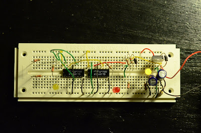
The previous image shows the components used for the 5VDC and oscillating 5V to 0V signal on the right (everything to the right of the red diode). I added another capacitor after the MOSFET just to make sure everything was properly smoothed out. The yellow diode to the far right indicates that the device is powered. The rest of the stuff (red diode and to the left) is used for counting.


I used two NTE4017B decade counting circuits which conveniently let you count between 1 and 10. Go to www.alldatasheet.com to find information on this circuit. The first one (right) counts up to 10, which means that a pulse is emitted from the circuit at a frequency of 6 Hz. The second one (left) counts up to 6, which means that a pulse is emitted from the circuit at a frequency of 1 Hz. The red diode flickers at 6 Hz and the left yellow diode flickers at 1 Hz. The two resistors on the far left do nothing (sorry, I forgot to remove them before I took the pictures!)

Again, sorry, I will submit schematics soon. I only put this together yesterday.

Until next time!


share on: facebook

Timing is Everything

BRIEF RANT: What is wrong with Radioshack and Fry's electronics!? I understand that if you are like most of my friends you will roll your eyes at what I'm about to say, but if you are an avid electronic hobbyist, I hope you understand my frustration. The problem is that I can't find any stupid crystal oscillators! As I mentioned briefly in my previous post, they provide very accurate pulses at a high frequency that you can use to provide very precise timing. They are ubiquitous in hobby radio applications (here is why I am appalled at Radioshack) and are necessary to run programmable circuits, which are widely available at Fry's, WHO DOES NOT SELL CRYSTAL OSCILLATORS! So, if you want to get every component at one store EXCEPT the one you desperately need, go to Fry's.

Well, at least I thought I needed a crystal oscillator...

Turns out you can get extremely accurate timing based off of the 60Hz AC signal from your wall outlet. Apparently the power company will oscillate the AC signal at exactly 60 pulses a second every minute, every hour, and every day of the year. It's supposed to be one of the most accurate methods of keeping good time. I have seen a few examples of circuits using this method of timing on Hackaday.com, but I felt they left out a few important points. Hopefully the next few posts will clear this up. The only issue is that my nixie power supply runs off of 9VDC. So I have decided to put a transformer directly onto the board, meaning I will have direct access to the oscillating signal. Unfortunately, I have never-before tinkered with an AC signal.

See you next time!


share on: facebook

Nixie Tube Power Supply (Part 2)

Sorry about the lack of posts lately. I have been crazy busy with work, not to mention the three vacations I have had back to back (believe it or not, that can be a bit tiring--but don't get me wrong, I would do it all over again). Anyways, enough about me, I have pictures of the power supply!


That large black cylinder is the inductor (in case you were wondering). Look at the previous post for a schematic. I got almost every single part from Digikey. Aside from the inductor, I received enough parts to make almost five of these power supplies with a final cost of around $40-$50. Not too bad if you ask me. Buying in bulk obviously reduces the prices even further. Not shown is the 9VDC power supply, which I am currently borrowing from my other nixie clock.


I thought originally that I had purchased a high-voltage 2.2uF capacitor (C4), but it turns out I missed it when I did the ordering. The large gray rectangular box is a 0.68uF capacitor rated at 310V. I yanked it from a broken computer power supply I had sitting around. I would have been pretty angry if I hadn't found it... crisis averted! Turns out the 0.68uF capacitor works just fine instead of the 2.2uF cap.


The back-side doesn't look too pretty, but it's a project board, what do you expect?? I'll upgrade to PCB (printed circuit board) eventually!

So, success! I get an output of 170VDC (adjustable by adjusting the potentiometer--the blue rectangular box) out of the red wire (red means DANGER!). I also get a convenient 5VDC output I can use for the integrated circuits out of the yellow wire. Black is common for both outputs. I'll see if I can't eventually post a picture of the nixie tube hooked up. I know this works from experience, but it would be nice to show it on the blog.

Next, I need to figure out a way to get the timing on the clock right. This has been bothering me for a bit since I would like to avoid using PICs (programmable integrated circuits), but the only reliable way to get a timed pulse that will be accurate over months or years with a DC input is to use a crystal oscillator. These puppies put out thousands to millions of pulses per second... bringing that down to 1 pulse per second will take a large number of divider circuits. Ok, I'll get back to you on this! 'Till next time!

share on: facebook